Volumetric Clouds with Clojure and LWJGL
Volumetric clouds are commonly used in flight simulators and visual effects. For a introductory video see Sebastian Lague’s video “Coding Adventure: Clouds. This article gets you started with computing and rendering volumetric clouds.
Dependencies
To download the required libraries, we use a deps.edn file with the following content:
{:deps
 {
  org.clojure/clojure {:mvn/version "1.12.3"}
  org.scicloj/noj     {:mvn/version "2-beta18"}
  midje/midje         {:mvn/version "1.10.10"}
  generateme/fastmath {:mvn/version "3.0.0-alpha4"}
  comb/comb           {:mvn/version "1.0.0"}
  }
}
We are going to import the following methods and namespaces:
(require '[clojure.math :refer (PI sqrt cos sin tan to-radians pow floor)]
         '[midje.sweet :refer (fact facts tabular => roughly)]
         '[fastmath.vector :refer (vec2 vec3 add mult sub div mag dot normalize)]
         '[fastmath.matrix :refer (mat->float-array mulm
                                   rotation-matrix-3d-x rotation-matrix-3d-y)]
         '[tech.v3.datatype :as dtype]
         '[tech.v3.tensor :as tensor]
         '[tech.v3.datatype.functional :as dfn]
         '[tablecloth.api :as tc]
         '[scicloj.tableplot.v1.plotly :as plotly]
         '[tech.v3.libs.buffered-image :as bufimg]
         '[comb.template :as template])
(import '[org.lwjgl.opengl GL11]
        '[org.lwjgl BufferUtils]
        '[org.lwjgl.glfw GLFW]
        '[org.lwjgl.opengl GL GL11 GL12 GL13 GL15 GL20 GL30 GL32 GL42])
Worley noise
Worley noise is a type of structured noise which is defined for each pixel using the distance to the nearest seed point.
Noise parameters
First we define a function to create parameters of the noise.
- size is the size of each dimension of the noise array
- divisions is the number of subdividing cells in each dimension
- dimensions is the number of dimensions
(defn make-noise-params
  [size divisions dimensions]
  {:size size :divisions divisions :cellsize (/ size divisions) :dimensions dimensions})
Here is a corresponding Midje test. Note that ideally you practise Test Driven Development (TDD), i.e. you start with writing one failing test. Because this is a Clojure notebook, the unit tests are displayed after the implementation.
(fact "Noise parameter initialisation"
(make-noise-params 256 8 2) => {:size 256 :divisions 8 :cellsize 32 :dimensions 2})true2D and 3D vectors
Next we need a function which allows us to create 2D or 3D vectors depending on the number of input parameters.
(defn vec-n
  ([x y] (vec2 x y))
  ([x y z] (vec3 x y z)))
(facts "Generic vector function for creating 2D and 3D vectors"
(vec-n 2 3) => (vec2 2 3)
(vec-n 2 3 1) => (vec3 2 3 1))trueRandom points
The following method generates a random point in a cell specified by the cell indices.
(defn random-point-in-cell
  [{:keys [cellsize]} & indices]
  (let [random-seq (repeatedly #(rand cellsize))
        dimensions (count indices)]
    (add (mult (apply vec-n (reverse indices)) cellsize)
         (apply vec-n (take dimensions random-seq)))))
We test the method by replacing the random function with a deterministic function.
(facts "Place random point in a cell"
       (with-redefs [rand (fn [s] (* 0.5 s))]
         (random-point-in-cell {:cellsize 1} 0 0) => (vec2 0.5 0.5)
         (random-point-in-cell {:cellsize 2} 0 0) => (vec2 1.0 1.0)
         (random-point-in-cell {:cellsize 2} 0 3) => (vec2 7.0 1.0)
         (random-point-in-cell {:cellsize 2} 2 0) => (vec2 1.0 5.0)
(random-point-in-cell {:cellsize 2} 2 3 5) => (vec3 11.0 7.0 5.0)))trueWe can now use the random-point method to generate a grid of random points. The grid is represented using a tensor from the dtype-next library.
(defn random-points
  [{:keys [divisions dimensions] :as params}]
  (tensor/clone
    (tensor/compute-tensor (repeat dimensions divisions)
                           (partial random-point-in-cell params))))
(facts "Greate grid of random points"
(let [params-2d (make-noise-params 32 8 2)
params-3d (make-noise-params 32 8 3)]
(with-redefs [rand (fn [s] (* 0.5 s))]
(dtype/shape (random-points params-2d)) => [8 8]
((random-points params-2d) 0 0) => (vec2 2.0 2.0)
((random-points params-2d) 0 3) => (vec2 14.0 2.0)
((random-points params-2d) 2 0) => (vec2 2.0 10.0)
(dtype/shape (random-points params-3d)) => [8 8 8]
((random-points params-3d) 2 3 5) => (vec3 22.0 14.0 10.0))))trueHere is a scatter plot showing one random point placed in each cell.
(let [points  (tensor/reshape (random-points (make-noise-params 256 8 2)) [(* 8 8)])
      scatter (tc/dataset {:x (map first points) :y (map second points)})]
  (-> scatter
      (plotly/base {:=title "Random points"})
      (plotly/layer-point {:=x :x :=y :y})))
Modular distance
In order to get a periodic noise array, we need to component-wise wrap around distance vectors.
(defn mod-vec
  [{:keys [size]} v]
  (let [size2 (/ size 2)
        wrap  (fn [x] (-> x (+ size2) (mod size) (- size2)))]
    (apply vec-n (map wrap v))))
(facts "Wrap around components of vector to be within -size/2..size/2"
(mod-vec {:size 8} (vec2 2 3)) => (vec2 2 3)
(mod-vec {:size 8} (vec2 5 2)) => (vec2 -3 2)
(mod-vec {:size 8} (vec2 2 5)) => (vec2 2 -3)
(mod-vec {:size 8} (vec2 -5 2)) => (vec2 3 2)
(mod-vec {:size 8} (vec2 2 -5)) => (vec2 2 3)
(mod-vec {:size 8} (vec3 2 3 1)) => (vec3 2 3 1)
(mod-vec {:size 8} (vec3 5 2 1)) => (vec3 -3 2 1)
(mod-vec {:size 8} (vec3 2 5 1)) => (vec3 2 -3 1)
(mod-vec {:size 8} (vec3 2 3 5)) => (vec3 2 3 -3)
(mod-vec {:size 8} (vec3 -5 2 1)) => (vec3 3 2 1)
(mod-vec {:size 8} (vec3 2 -5 1)) => (vec3 2 3 1)
(mod-vec {:size 8} (vec3 2 3 -5)) => (vec3 2 3 3))trueUsing the mod-dist function we can calculate the distance between two points in the periodic noise array.
(defn mod-dist
  [params a b]
  (mag (mod-vec params (sub b a))))
The tabular macro implemented by Midje is useful for running parametrized tests.
(tabular "Wrapped distance of two points"
         (fact (mod-dist {:size 8} (vec2 ?ax ?ay) (vec2 ?bx ?by)) => ?result)
         ?ax ?ay ?bx ?by ?result
         0   0   0   0   0.0
         0   0   2   0   2.0
         0   0   5   0   3.0
         0   0   0   2   2.0
         0   0   0   5   3.0
         2   0   0   0   2.0
         5   0   0   0   3.0
         0   2   0   0   2.0
0 5 0 0 3.0)trueModular lookup
We also need to lookup elements with wrap around. We recursively use tensor/select and then finally the tensor as a function to lookup along each axis.
(defn wrap-get
  [t & args]
  (if (> (count (dtype/shape t)) (count args))
    (apply tensor/select t (map mod args (dtype/shape t)))
    (apply t (map mod args (dtype/shape t)))))
A tensor with index vectors is used to test the lookup.
(facts "Wrapped lookup of tensor values"
       (let [t (tensor/compute-tensor [4 6] vec2)]
         (wrap-get t 2 3) => (vec2 2 3)
         (wrap-get t 2 7) => (vec2 2 1)
         (wrap-get t 5 3) => (vec2 1 3)
(wrap-get (wrap-get t 5) 3) => (vec2 1 3)))trueThe following function converts a noise coordinate to the index of a cell in the random point array.
(defn division-index
  [{:keys [cellsize]} x]
  (int (floor (/ x cellsize))))
(facts "Convert coordinate to division index"
(division-index {:cellsize 4} 3.5) => 0
(division-index {:cellsize 4} 7.5) => 1
(division-index {:cellsize 4} -0.5) => -1)trueGetting indices of Neighbours
The following function determines the neighbouring indices of a cell recursing over each dimension.
(defn neighbours
  [& args]
  (if (seq args)
    (mapcat (fn [v] (map (fn [delta] (into [(+ (first args) delta)] v)) [-1 0 1]))
            (apply neighbours (rest args)) )
    [[]]))
(facts "Get neighbouring indices"
(neighbours) => [[]]
(neighbours 0) => [[-1] [0] [1]]
(neighbours 3) => [[2] [3] [4]]
(neighbours 1 10) => [[0 9] [1 9] [2 9] [0 10] [1 10] [2 10] [0 11] [1 11] [2 11]])trueSampling Worley noise
Using above functions one can now implement Worley noise. For each pixel the distance to the closest seed point is calculated. This is achieved by determining the distance to each random point in all neighbouring cells and then taking the minimum.
(defn worley-noise
  [{:keys [size dimensions] :as params}]
  (let [random-points (random-points params)]
    (tensor/clone
      (tensor/compute-tensor
        (repeat dimensions size)
        (fn [& coords]
            (let [center   (map #(+ % 0.5) coords)
                  division (map (partial division-index params) center)]
              (apply min
                     (for [neighbour (apply neighbours division)]
                          (mod-dist params (apply vec-n (reverse center))
                                    (apply wrap-get random-points neighbour))))))
        :double))))
Here a 256 × 256 Worley noise tensor is created.
(def worley (worley-noise (make-noise-params 256 8 2)))The values are inverted and normalised to be between 0 and 255.
(def worley-norm
  (dfn/* (/ 255 (- (dfn/reduce-max worley) (dfn/reduce-min worley)))
         (dfn/- (dfn/reduce-max worley) worley)))
Finally one can display the noise.
(bufimg/tensor->image worley-norm)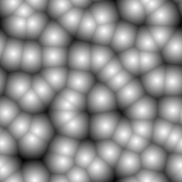
Perlin noise
Perlin noise is generated by choosing a random gradient vector at each cell corner. The noise tensor’s intermediate values are interpolated with a continuous function, utilizing the gradient at the corner points.
Random gradients
The 2D or 3D gradients are generated by creating a vector where each component is set to a random number between -1 and 1. Random vectors are generated until the vector length is greater 0 and lower or equal to 1. The vector then is normalized and returned. Random vectors outside the unit circle or sphere are discarded in order to achieve a uniform distribution on the surface of the unit circle or sphere.
(defn random-gradient
  [& args]
  (loop [args args]
        (let [random-vector (apply vec-n (map (fn [_x] (- (rand 2.0) 1.0)) args))
              vector-length (mag random-vector)]
          (if (and (> vector-length 0.0) (<= vector-length 1.0))
            (div random-vector vector-length)
            (recur args)))))
The function below serves as a Midje checker for a vector with an approximate expected value.
(defn roughly-vec
  [expected error]
  (fn [actual]
      (<= (mag (sub actual expected)) error)))
In the following tests, the random function is again replaced with a deterministic function.
(facts "Create unit vector with random direction"
       (with-redefs [rand (constantly 0.5)]
         (random-gradient 0 0)
         => (roughly-vec (vec2 (- (sqrt 0.5)) (- (sqrt 0.5))) 1e-6))
       (with-redefs [rand (constantly 1.5)]
         (random-gradient 0 0)
=> (roughly-vec (vec2 (sqrt 0.5) (sqrt 0.5)) 1e-6)))trueThe random gradient function is then used to generate a field of random gradients.
(defn random-gradients
 [{:keys [divisions dimensions]}]
 (tensor/clone (tensor/compute-tensor (repeat dimensions divisions) random-gradient)))
The function is verified to correctly generate 2D and 3D random gradient fields.
(facts "Random gradients"
       (with-redefs [rand (constantly 1.5)]
         (dtype/shape (random-gradients {:divisions 8 :dimensions 2}))
         => [8 8]
         ((random-gradients {:divisions 8 :dimensions 2}) 0 0)
         => (roughly-vec (vec2 (sqrt 0.5) (sqrt 0.5)) 1e-6)
         (dtype/shape (random-gradients {:divisions 8 :dimensions 3})) => [8 8 8]
         ((random-gradients {:divisions 8 :dimensions 3}) 0 0 0)
=> (vec3 (/ 1 (sqrt 3)) (/ 1 (sqrt 3)) (/ 1 (sqrt 3)))))trueThe gradient field can be plotted with Plotly as a scatter plot of disconnected lines.
(let [gradients (tensor/reshape (random-gradients (make-noise-params 256 8 2))
                                [(* 8 8)])
      points    (tensor/reshape (tensor/compute-tensor [8 8] (fn [y x] (vec2 x y)))
                                [(* 8 8)])
      scatter   (tc/dataset {:x (mapcat (fn [point gradient]
                                            [(point 0)
                                             (+ (point 0) (* 0.5 (gradient 0)))
                                             nil])
                                        points gradients)
                             :y (mapcat (fn [point gradient]
                                            [(point 1)
                                             (+ (point 1) (* 0.5 (gradient 1)))
                                             nil])
                                        points gradients)})]
  (-> scatter
      (plotly/base {:=title "Random gradients" :=mode "lines"})
      (plotly/layer-point {:=x :x :=y :y})))
Corner vectors
The next step is to determine the vectors to the corners of the cell for a given point. First we define a function to determine the fractional part of a number.
(defn frac
  [x]
  (- x (Math/floor x)))
(facts "Fractional part of floating point number"
(frac 0.25) => 0.25
(frac 1.75) => 0.75
(frac -0.25) => 0.75)trueThis function can be used to determine the relative position of a point in a cell.
(defn cell-pos
  [{:keys [cellsize]} point]
  (apply vec-n (map frac (div point cellsize))))
(facts "Relative position of point in a cell"
(cell-pos {:cellsize 4} (vec2 2 3)) => (vec2 0.5 0.75)
(cell-pos {:cellsize 4} (vec2 7 5)) => (vec2 0.75 0.25)
(cell-pos {:cellsize 4} (vec3 7 5 2)) => (vec3 0.75 0.25 0.5))trueA 2 × 2 tensor of corner vectors can be computed by subtracting the corner coordinates from the point coordinates.
(defn corner-vectors
  [{:keys [dimensions] :as params} point]
  (let [cell-pos (cell-pos params point)]
    (tensor/compute-tensor
      (repeat dimensions 2)
      (fn [& args] (sub cell-pos (apply vec-n (reverse args)))))))
(facts "Compute relative vectors from cell corners to point in cell"
(let [corners2 (corner-vectors {:cellsize 4 :dimensions 2} (vec2 7 6))
corners3 (corner-vectors {:cellsize 4 :dimensions 3} (vec3 7 6 5))]
(corners2 0 0) => (vec2 0.75 0.5)
(corners2 0 1) => (vec2 -0.25 0.5)
(corners2 1 0) => (vec2 0.75 -0.5)
(corners2 1 1) => (vec2 -0.25 -0.5)
(corners3 0 0 0) => (vec3 0.75 0.5 0.25)))trueExtract gradients of cell corners
The function below retrieves the gradient values at a cell’s corners, utilizing wrap-get for modular access. The result is a 2 × 2 tensor of gradient vectors.
(defn corner-gradients
  [{:keys [dimensions] :as params} gradients point]
  (let [division (map (partial division-index params) point)]
    (tensor/compute-tensor
      (repeat dimensions 2)
      (fn [& coords] (apply wrap-get gradients (map + (reverse division) coords))))))
(facts "Get 2x2 tensor of gradients from a larger tensor using wrap around"
(let [gradients2 (tensor/compute-tensor [4 6] (fn [y x] (vec2 x y)))
gradients3 (tensor/compute-tensor [4 6 8] (fn [z y x] (vec3 x y z))) ]
((corner-gradients {:cellsize 4 :dimensions 2} gradients2 (vec2 9 6)) 0 0)
=> (vec2 2 1)
((corner-gradients {:cellsize 4 :dimensions 2} gradients2 (vec2 9 6)) 0 1)
=> (vec2 3 1)
((corner-gradients {:cellsize 4 :dimensions 2} gradients2 (vec2 9 6)) 1 0)
=> (vec2 2 2)
((corner-gradients {:cellsize 4 :dimensions 2} gradients2 (vec2 9 6)) 1 1)
=> (vec2 3 2)
((corner-gradients {:cellsize 4 :dimensions 2} gradients2 (vec2 23 15)) 1 1)
=> (vec2 0 0)
((corner-gradients {:cellsize 4 :dimensions 3} gradients3 (vec3 9 6 3)) 0 0 0)
=> (vec3 2 1 0)))trueInfluence values
The influence value is the function value of the function with the selected random gradient at a corner.
(defn influence-values
  [gradients vectors]
  (tensor/compute-tensor
    (repeat (count (dtype/shape gradients)) 2)
    (fn [& args] (dot (apply gradients args) (apply vectors args)))
    :double))
(facts "Compute influence values from corner vectors and gradients"
(let [gradients2 (tensor/compute-tensor [2 2] (fn [_y x] (vec2 x 10)))
vectors2 (tensor/compute-tensor [2 2] (fn [y _x] (vec2 1 y)))
influence2 (influence-values gradients2 vectors2)
gradients3 (tensor/compute-tensor [2 2 2] (fn [z y x] (vec3 x y z)))
vectors3 (tensor/compute-tensor [2 2 2] (fn [_z _y _x] (vec3 1 10 100)))
influence3 (influence-values gradients3 vectors3)]
(influence2 0 0) => 0.0
(influence2 0 1) => 1.0
(influence2 1 0) => 10.0
(influence2 1 1) => 11.0
(influence3 1 1 1) => 111.0))trueInterpolating the influence values
For interpolation the following “ease curve” is used.
(defn ease-curve
  [t]
  (-> t (* 6.0) (- 15.0) (* t) (+ 10.0) (* t t t)))
(facts "Monotonously increasing function with zero derivative at zero and one"
(ease-curve 0.0) => 0.0
(ease-curve 0.25) => (roughly 0.103516 1e-6)
(ease-curve 0.5) => 0.5
(ease-curve 0.75) => (roughly 0.896484 1e-6)
(ease-curve 1.0) => 1.0)trueThe ease curve monotonously increases in the interval from zero to one.
(-> (tc/dataset {:t (range 0.0 1.025 0.025)
                 :ease (map ease-curve (range 0.0 1.025 0.025))})
    (plotly/base {:=title "Ease Curve"})
    (plotly/layer-line {:=x :t :=y :ease}))
The interpolation weights are recursively calculated from the ease curve and the coordinate distances of the point to upper and lower cell boundary.
(defn interpolation-weights
  ([params point]
   (interpolation-weights (cell-pos params point)))
  ([pos]
   (if (seq pos)
     (let [w1   (- 1.0 (last pos))
           w2   (last pos)
           elem (interpolation-weights (butlast pos))]
       (tensor/->tensor [(dfn/* (ease-curve w1) elem) (dfn/* (ease-curve w2) elem)]))
     1.0)))
(facts "Interpolation weights"
(let [weights2 (interpolation-weights {:cellsize 8} (vec2 2 7))
weights3 (interpolation-weights {:cellsize 8} (vec3 2 7 3))]
(weights2 0 0) => (roughly 0.014391 1e-6)
(weights2 0 1) => (roughly 0.001662 1e-6)
(weights2 1 0) => (roughly 0.882094 1e-6)
(weights2 1 1) => (roughly 0.101854 1e-6)
(weights3 0 0 0) => (roughly 0.010430 1e-6)))trueSampling Perlin noise
A Perlin noise sample is computed by
- Getting the random gradients for the cell corners.
- Getting the corner vectors for the cell corners.
- Computing the influence values which have the desired gradients.
- Determining the interpolation weights.
- Computing the weighted sum of the influence values.
(defn perlin-sample
  [params gradients point]
  (let [gradients (corner-gradients params gradients point)
        vectors   (corner-vectors params point)
        influence (influence-values gradients vectors)
        weights   (interpolation-weights params point)]
    (dfn/reduce-+ (dfn/* weights influence))))
Now one can sample the Perlin noise by performing above computation for the center of each pixel.
(defn perlin-noise
  [{:keys [size dimensions] :as params}]
  (let [gradients (random-gradients params)]
    (tensor/clone
      (tensor/compute-tensor
        (repeat dimensions size)
        (fn [& args]
            (let [center (apply vec-n (map #(+ % 0.5) (reverse args)))]
              (perlin-sample params gradients center)))
        :double))))
Here a 256 × 256 Perlin noise tensor is created.
(def perlin (perlin-noise (make-noise-params 256 8 2)))The values are normalised to be between 0 and 255.
(def perlin-norm
  (dfn/* (/ 255 (- (dfn/reduce-max perlin) (dfn/reduce-min perlin)))
         (dfn/- perlin (dfn/reduce-min perlin))))
Finally one can display the noise.
(bufimg/tensor->image perlin-norm)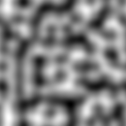
Mixing noise values
Combination of Worley and Perlin noise
You can blend Worley and Perlin noise by performing a linear combination of both.
(def perlin-worley-norm (dfn/+ (dfn/* 0.3 perlin-norm) (dfn/* 0.7 worley-norm)))Here for example is the average of Perlin and Worley noise.
(bufimg/tensor->image (dfn/+ (dfn/* 0.5 perlin-norm) (dfn/* 0.5 worley-norm)))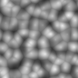
Interpolation
One can linearly interpolate tensor values by recursing over the dimensions as follows.
(defn interpolate
  [tensor & args]
  (if (seq args)
    (let [x  (first args)
          xc (- x 0.5)
          xf (frac xc)
          x0 (int (Math/floor xc))]
      (+ (* (- 1.0 xf) (apply interpolate (wrap-get tensor      x0 ) (rest args)))
         (*        xf  (apply interpolate (wrap-get tensor (inc x0)) (rest args)))))
    tensor))
Here x-, y-, and z-ramps are used to test that interpolation works.
(facts "Interpolate values of tensor"
       (let [x2 (tensor/compute-tensor [4 6] (fn [_y x] x))
             y2 (tensor/compute-tensor [4 6] (fn [y _x] y))
             x3 (tensor/compute-tensor [4 6 8] (fn [_z _y x] x))
             y3 (tensor/compute-tensor [4 6 8] (fn [_z y _x] y))
             z3 (tensor/compute-tensor [4 6 8] (fn [z _y _x] z))]
         (interpolate x2 2.5 3.5) => 3.0
         (interpolate y2 2.5 3.5) => 2.0
         (interpolate x2 2.5 4.0) => 3.5
         (interpolate y2 3.0 3.5) => 2.5
         (interpolate x2 0.0 0.0) => 2.5
         (interpolate y2 0.0 0.0) => 1.5
         (interpolate x3 2.5 3.5 5.5) => 5.0
         (interpolate y3 2.5 3.5 3.0) => 3.0
(interpolate z3 2.5 3.5 5.5) => 2.0))trueOctaves of noise
Fractal Brownian Motion is implemented by computing a weighted sum of the same base noise function using different frequencies.
(defn fractal-brownian-motion
  [base octaves & args]
  (let [scales (take (count octaves) (iterate #(* 2 %) 1))]
    (reduce + 0.0
            (map (fn [amplitude scale] (* amplitude (apply base (map #(* scale %) args))))
                 octaves scales))))
Here the Fractal Brownian Motion is tested using an alternating 1D function and later a 2D checkboard function.
(facts "Fractal Brownian motion"
       (let [base1 (fn [x] (if (>= (mod x 2.0) 1.0) 1.0 0.0))
             base2 (fn [y x] (if (= (Math/round (mod y 2.0)) (Math/round (mod x 2.0)))
                               0.0 1.0))]
         (fractal-brownian-motion base2 [1.0] 0 0) => 0.0
         (fractal-brownian-motion base2 [1.0] 0 1) => 1.0
         (fractal-brownian-motion base2 [1.0] 1 0) => 1.0
         (fractal-brownian-motion base2 [1.0] 1 1) => 0.0
         (fractal-brownian-motion base2 [0.5] 0 1) => 0.5
         (fractal-brownian-motion base2 [] 0 1) => 0.0
         (fractal-brownian-motion base2 [0.0 1.0] 0 0) => 0.0
         (fractal-brownian-motion base2 [0.0 1.0] 0.0 0.5) => 1.0
         (fractal-brownian-motion base2 [0.0 1.0] 0.5 0.0) => 1.0
         (fractal-brownian-motion base2 [0.0 1.0] 0.5 0.5) => 0.0
         (fractal-brownian-motion base1 [1.0] 0) => 0.0
         (fractal-brownian-motion base1 [1.0] 1) => 1.0
         (fractal-brownian-motion base1 [0.0 1.0] 0.0) => 0.0
(fractal-brownian-motion base1 [0.0 1.0] 0.5) => 1.0))trueRemapping and clamping
The remap function is used to map a range of values of an input tensor to a different range.
(defn remap
  [value low1 high1 low2 high2]
  (dfn/+ low2 (dfn/* (dfn/- value low1) (/ (- high2 low2) (- high1 low1)))))
(tabular "Remap values of tensor"
(fact ((remap (tensor/->tensor [?value]) ?low1 ?high1 ?low2 ?high2) 0)
=> ?expected)
?value ?low1 ?high1 ?low2 ?high2 ?expected
0 0 1 0 1 0
1 0 1 0 1 1
0 0 1 2 3 2
1 0 1 2 3 3
2 2 3 0 1 0
3 2 3 0 1 1
1 0 2 0 4 2)trueThe clamp function is used to element-wise clamp values to a range.
(defn clamp
  [value low high]
  (dfn/max low (dfn/min value high)))
(tabular "Clamp values of tensor"
(fact ((clamp (tensor/->tensor [?value]) ?low ?high) 0) => ?expected)
?value ?low ?high ?expected
2 2 3 2
3 2 3 3
0 2 3 2
4 2 3 3)trueGenerating octaves of noise
The octaves function is used to create a series of decreasing weights and normalize them so that they add up to 1.
(defn octaves
  [n decay]
  (let [series (take n (iterate #(* % decay) 1.0))
        sum    (apply + series)]
    (mapv #(/ % sum) series)))
Here is an example of noise weights decreasing by 50% at each octave.
(octaves 4 0.5)[0.5333333333333333
0.26666666666666666
0.13333333333333333
0.06666666666666667]Now a noise array can be generated using octaves of noise.
(defn noise-octaves
  [tensor octaves low high]
  (tensor/clone
    (clamp
      (remap
        (tensor/compute-tensor (dtype/shape tensor)
                               (fn [& args]
                                   (apply fractal-brownian-motion
                                     (partial interpolate tensor)
                                     octaves
                                     (map #(+ % 0.5) args)))
                               :double)
        low high 0 255)
      0 255)))
2D examples
Here is an example of 4 octaves of Worley noise.
(bufimg/tensor->image (noise-octaves worley-norm (octaves 4 0.6) 120 230))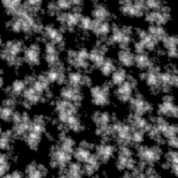
Here is an example of 4 octaves of Perlin noise.
(bufimg/tensor->image (noise-octaves perlin-norm (octaves 4 0.6) 120 230))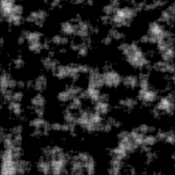
Here is an example of 4 octaves of mixed Perlin and Worley noise.
(bufimg/tensor->image (noise-octaves perlin-worley-norm (octaves 4 0.6) 120 230))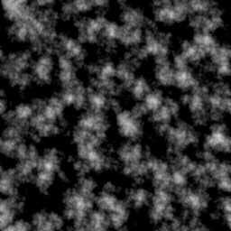
OpenGL rendering
OpenGL initialization
In order to render the clouds we create a window and an OpenGL context. Note that we need to create an invisible window to get an OpenGL context, even though we are not going to draw to the window
(GLFW/glfwInit)true(def window-width 640)(def window-height 480)(GLFW/glfwDefaultWindowHints)nil(GLFW/glfwWindowHint GLFW/GLFW_VISIBLE GLFW/GLFW_FALSE)nil(def window (GLFW/glfwCreateWindow window-width window-height "Invisible Window" 0 0))(GLFW/glfwMakeContextCurrent window)nil(GL/createCapabilities)#object[org.lwjgl.opengl.GLCapabilities 0x7fa20c48 "org.lwjgl.opengl.GLCapabilities@7fa20c48"]Compiling and linking shader programs
The following method is used compile a shader program.
(defn make-shader [source shader-type]
  (let [shader (GL20/glCreateShader shader-type)]
    (GL20/glShaderSource shader source)
    (GL20/glCompileShader shader)
    (when (zero? (GL20/glGetShaderi shader GL20/GL_COMPILE_STATUS))
      (throw (Exception. (GL20/glGetShaderInfoLog shader 1024))))
    shader))
The different shaders are then linked to become a shader program using the following method.
(defn make-program [& shaders]
  (let [program (GL20/glCreateProgram)]
    (doseq [shader shaders]
           (GL20/glAttachShader program shader)
           (GL20/glDeleteShader shader))
    (GL20/glLinkProgram program)
    (when (zero? (GL20/glGetProgrami program GL20/GL_LINK_STATUS))
      (throw (Exception. (GL20/glGetProgramInfoLog program 1024))))
    program))
This method is used to perform both compilation and linking of vertex shaders and fragment shaders.
(defn make-program-with-shaders
  [vertex-sources fragment-sources]
  (let [vertex-shaders   (map #(make-shader % GL20/GL_VERTEX_SHADER) vertex-sources)
        fragment-shaders (map #(make-shader % GL20/GL_FRAGMENT_SHADER) fragment-sources)
        program          (apply make-program (concat vertex-shaders fragment-shaders))]
    program))
In order to pass data to LWJGL methods, we need to be able to convert arrays to Java buffer objects.
(defmacro def-make-buffer [method create-buffer]
  `(defn ~method [data#]
     (let [buffer# (~create-buffer (count data#))]
       (.put buffer# data#)
       (.flip buffer#)
       buffer#)))
Setup of vertex data
Above macro is used to define methods for creating float, int, and byte buffer objects.
(def-make-buffer make-float-buffer BufferUtils/createFloatBuffer)#'volumetric-clouds.main/make-float-buffer(def-make-buffer make-int-buffer BufferUtils/createIntBuffer)#'volumetric-clouds.main/make-int-buffer(def-make-buffer make-byte-buffer BufferUtils/createByteBuffer)#'volumetric-clouds.main/make-byte-bufferWe implement a method to create a vertex array object (VAO) with a vertex buffer object (VBO) and an index buffer object (IBO).
(defn setup-vao [vertices indices]
  (let [vao (GL30/glGenVertexArrays)
        vbo (GL15/glGenBuffers)
        ibo (GL15/glGenBuffers)]
    (GL30/glBindVertexArray vao)
    (GL15/glBindBuffer GL15/GL_ARRAY_BUFFER vbo)
    (GL15/glBufferData GL15/GL_ARRAY_BUFFER (make-float-buffer vertices)
                       GL15/GL_STATIC_DRAW)
    (GL15/glBindBuffer GL15/GL_ELEMENT_ARRAY_BUFFER ibo)
    (GL15/glBufferData GL15/GL_ELEMENT_ARRAY_BUFFER (make-int-buffer indices)
                       GL15/GL_STATIC_DRAW)
    {:vao vao :vbo vbo :ibo ibo}))
We also define the corresponding destructor for the vertex data.
(defn teardown-vao [{:keys [vao vbo ibo]}]
  (GL15/glBindBuffer GL15/GL_ELEMENT_ARRAY_BUFFER 0)
  (GL15/glDeleteBuffers ibo)
  (GL15/glBindBuffer GL15/GL_ARRAY_BUFFER 0)
  (GL15/glDeleteBuffers vbo)
  (GL30/glBindVertexArray 0)
  (GL15/glDeleteBuffers vao))
Offscreen rendering to a texture
The following method is used to create an empty 2D RGBA floating point texture
(defn make-texture-2d
  [width height]
  (let [texture (GL11/glGenTextures)]
    (GL11/glBindTexture GL11/GL_TEXTURE_2D texture)
    (GL11/glTexParameteri GL12/GL_TEXTURE_2D GL11/GL_TEXTURE_MIN_FILTER GL11/GL_LINEAR)
    (GL11/glTexParameteri GL12/GL_TEXTURE_2D GL11/GL_TEXTURE_MAG_FILTER GL11/GL_LINEAR)
    (GL11/glTexParameteri GL12/GL_TEXTURE_2D GL11/GL_TEXTURE_WRAP_S GL11/GL_REPEAT)
    (GL11/glTexParameteri GL12/GL_TEXTURE_2D GL11/GL_TEXTURE_WRAP_T GL11/GL_REPEAT)
    (GL42/glTexStorage2D GL11/GL_TEXTURE_2D 1 GL30/GL_RGBA32F width height)
    texture))
We define a method to convert a Java buffer object to a floating point array.
(defn float-buffer->array
  "Convert float buffer to float array"
  [buffer]
  (let [result (float-array (.limit buffer))]
    (.get buffer result)
    (.flip buffer)
    result))
The following method copies texture data into a Java buffer and then converts it to a floating point array.
(defn read-texture-2d
  [texture width height]
  (let [buffer (BufferUtils/createFloatBuffer (* height width 4))]
    (GL11/glBindTexture GL11/GL_TEXTURE_2D texture)
    (GL11/glGetTexImage GL11/GL_TEXTURE_2D 0 GL12/GL_RGBA GL11/GL_FLOAT buffer)
    (float-buffer->array buffer)))
This method sets up rendering using a specified texture as a framebuffer and then executes the body.
(defmacro framebuffer-render
  [texture width height & body]
  `(let [fbo# (GL30/glGenFramebuffers)]
     (try
       (GL30/glBindFramebuffer GL30/GL_FRAMEBUFFER fbo#)
       (GL11/glBindTexture GL11/GL_TEXTURE_2D ~texture)
       (GL32/glFramebufferTexture GL30/GL_FRAMEBUFFER GL30/GL_COLOR_ATTACHMENT0
                                  ~texture 0)
       (GL20/glDrawBuffers (volumetric-clouds.main/make-int-buffer
                             (int-array [GL30/GL_COLOR_ATTACHMENT0])))
       (GL11/glViewport 0 0 ~width ~height)
       ~@body
       (finally
         (GL30/glBindFramebuffer GL30/GL_FRAMEBUFFER 0)
         (GL30/glDeleteFramebuffers fbo#)))))
We also create a method to set up the layout of the vertex buffer. Our vertex data is only going to contain 3D coordinates of points.
(defn setup-point-attribute
  [program]
  (let [point-attribute (GL20/glGetAttribLocation program "point")]
    (GL20/glVertexAttribPointer point-attribute 3 GL11/GL_FLOAT false
                                (* 3 Float/BYTES) (* 0 Float/BYTES))
    (GL20/glEnableVertexAttribArray point-attribute)))
We are going to use a simple background quad to perform volumetric rendering.
(defn setup-quad-vao
  []
  (let [vertices (float-array [ 1.0  1.0 0.0,
                               -1.0  1.0 0.0,
                                1.0 -1.0 0.0,
                               -1.0 -1.0 0.0])
        indices  (int-array [0 1 3 2])]
    (setup-vao vertices indices)))
We now have all definitions ready to implement rendering of an image.
(defmacro render-array
  [width height & body]
  `(let [texture# (volumetric-clouds.main/make-texture-2d ~width ~height)]
     (try
       (volumetric-clouds.main/framebuffer-render texture# ~width ~height ~@body)
       (volumetric-clouds.main/read-texture-2d texture# ~width ~height)
       (finally
         (GL11/glDeleteTextures texture#)))))
The following method creates a program and the quad VAO and sets up the memory layout. The program and VAO are then used to render a single pixel. Using this method we can write unit tests for OpenGL shaders!
(defn render-pixel
  [vertex-sources fragment-sources]
  (let [program (make-program-with-shaders vertex-sources fragment-sources)
        vao     (setup-quad-vao)]
    (setup-point-attribute program)
    (try
      (render-array 1 1
                    (GL20/glUseProgram program)
                    (GL11/glDrawElements GL11/GL_QUADS 4 GL11/GL_UNSIGNED_INT 0))
      (finally
        (teardown-vao vao)
        (GL20/glDeleteProgram program)))))
We are going to use a simple vertex shader to simply pass through the points from the vertex buffer without any transformations.
(def vertex-passthrough
"#version 130
in vec3 point;
void main()
{
  gl_Position = vec4(point, 1);
}")
The following fragment shader is used to test rendering white pixels.
(def fragment-test
"#version 130
out vec4 fragColor;
void main()
{
  fragColor = vec4(1, 1, 1, 1);
}")
We can now render a single white RGBA pixel using the graphics card.
(render-pixel [vertex-passthrough] [fragment-test])[1.0, 1.0, 1.0, 1.0]Volumetric Clouds
Mocks and probing shaders
The following fragment shader creates a 3D checkboard pattern serving as a mock function below.
(def noise-mock
"#version 130
float noise(vec3 idx)
{
  ivec3 v = ivec3(floor(idx.x), floor(idx.y), floor(idx.z)) % 2;
  return ((v.x == 1) == (v.y == 1)) == (v.z == 1) ? 1.0 : 0.0;
}")
We can test this mock function using the following probing shader. Note that we are using the template macro of the comb Clojure library to generate the probing shader code from a template.
(def noise-probe
  (template/fn [x y z]
"#version 130
out vec4 fragColor;
float noise(vec3 idx);
void main()
{
  fragColor = vec4(noise(vec3(<%= x %>, <%= y %>, <%= z %>)));
}"))
Here multiple tests are run to test that the mock implements a checkboard pattern correctly.
(tabular "Test noise mock"
         (fact (nth (render-pixel [vertex-passthrough]
                                  [noise-mock (noise-probe ?x ?y ?z)]) 0)
               => ?result)
         ?x ?y ?z ?result
         0  0  0  0.0
         1  0  0  1.0
         0  1  0  1.0
         1  1  0  0.0
         0  0  1  1.0
         1  0  1  0.0
         0  1  1  0.0
1 1 1 1.0)trueOctaves of noise
We now implement a shader for 3D Fractal Brownian motion. Note that we can use the template macro to generate code for an arbitrary number of octaves.
(def noise-octaves
  (template/fn [octaves]
"#version 130
out vec4 fragColor;
float noise(vec3 idx);
float octaves(vec3 idx)
{
  float result = 0.0;
<% (doseq [multiplier octaves] %>
  result += <%= multiplier %> * noise(idx);
  idx *= 2.0;
<%= ) %>
  return result;
}"))
Again we use a probing shader to test the shader function.
(def octaves-probe
  (template/fn [x y z]
"#version 130
out vec4 fragColor;
float octaves(vec3 idx);
void main()
{
  fragColor = vec4(octaves(vec3(<%= x %>, <%= y %>, <%= z %>)));
}"))
A few unit tests with one or two octaves are sufficient to drive development of the shader function.
(tabular "Test octaves of noise"
         (fact (first (render-pixel [vertex-passthrough]
                                    [noise-mock (noise-octaves ?octaves)
                                     (octaves-probe ?x ?y ?z)]))
               => ?result)
         ?x  ?y ?z ?octaves  ?result
         0   0  0  [1.0]     0.0
         1   0  0  [1.0]     1.0
         1   0  0  [0.5]     0.5
         0.5 0  0  [0.0 1.0] 1.0
         0.5 0  0  [0.0 1.0] 1.0
1 0 0 [1.0 0.0] 1.0)trueShader for intersecting a ray with a box
The following shader implements intersection of a ray with an axis-aligned box. The shader function returns the distance of the near and far intersection with the box.
(def ray-box
"#version 130
vec2 ray_box(vec3 box_min, vec3 box_max, vec3 origin, vec3 direction)
{
  vec3 inv_dir = 1.0 / direction;
  vec3 smin = (box_min - origin) * inv_dir;
  vec3 smax = (box_max - origin) * inv_dir;
  vec3 s1 = min(smin, smax);
  vec3 s2 = max(smin, smax);
  float s_near = max(max(s1.x, s1.y), s1.z);
  float s_far = min(min(s2.x, s2.y), s2.z);
  if (isinf(s_near) || isinf(s_far))
    return vec2(0.0, 0.0);
  else
    return vec2(max(s_near, 0.0), max(0.0, s_far));
}")
The probing shader returns the near and far distance in the red and green channel of the fragment color.
(def ray-box-probe
  (template/fn [ox oy oz dx dy dz]
"#version 130
out vec4 fragColor;
vec2 ray_box(vec3 box_min, vec3 box_max, vec3 origin, vec3 direction);
void main()
{
  vec3 box_min = vec3(-1, -1, -1);
  vec3 box_max = vec3(1, 1, 1);
  vec3 origin = vec3(<%= ox %>, <%= oy %>, <%= oz %>);
  vec3 direction = vec3(<%= dx %>, <%= dy %>, <%= dz %>);
  fragColor = vec4(ray_box(box_min, box_max, origin, direction), 0, 0);
}"))
The ray-box shader is tested with different ray origins and directions.
(tabular "Test intersection of ray with box"
         (fact ((juxt first second)
                (render-pixel [vertex-passthrough]
                              [ray-box (ray-box-probe ?ox ?oy ?oz ?dx ?dy ?dz)]))
               => ?result)
         ?ox ?oy ?oz ?dx ?dy ?dz ?result
         -2   0   0   1   0   0  [1.0 3.0]
         -2   0   0   2   0   0  [0.5 1.5]
         -2   2   2   1   0   0  [0.0 0.0]
          0  -2   0   0   1   0  [1.0 3.0]
          0  -2   0   0   2   0  [0.5 1.5]
          2  -2   2   0   1   0  [0.0 0.0]
          0   0  -2   0   0   1  [1.0 3.0]
          0   0  -2   0   0   2  [0.5 1.5]
          2   2  -2   0   0   1  [0.0 0.0]
          0   0   0   1   0   0  [0.0 1.0]
2 0 0 1 0 0 [0.0 0.0])trueShader for light transfer through clouds
We test the light transfer through clouds using constant density fog.
(def fog
  (template/fn [v]
"#version 130
float fog(vec3 idx)
{
  return <%= v %>;
}"))
Volumetric rendering involves sampling cloud density along a ray and multiplying the transmittance values.
(def cloud-transfer
  (template/fn [noise step]
"#version 130
#define STEP <%= step %>
float <%= noise %>(vec3 idx);
float in_scatter(vec3 point, vec3 direction);
float shadow(vec3 point);
vec4 cloud_transfer(vec3 origin, vec3 direction, vec2 interval)
{
  vec4 result = vec4(0, 0, 0, 0);
  for (float t = interval.x + 0.5 * STEP; t < interval.y; t += STEP) {
    vec3 point = origin + direction * t;
    float density = <%= noise %>(point);
    float transmittance = exp(-density * STEP);
    vec3 color = vec3(in_scatter(point, direction) * shadow(point));
    result.rgb += color * (1.0 - result.a) * (1.0 - transmittance);
    result.a = 1.0 - (1.0 - result.a) * transmittance;
  };
  return result;
}"))
For now we also assume isotropic scattering of light in all directions. This is a placeholder for introducing Mie scattering later.
(def constant-scatter
"#version 130
float in_scatter(vec3 point, vec3 direction)
{
  return 1.0;
}")
Finally we assume that there is no shadow. This is a placeholder for introducing cloud shadows later.
(def no-shadow
"#version 130
float shadow(vec3 point)
{
  return 1.0;
}")
We can now test the color and opacity of the cloud using the following probing shader.
(def cloud-transfer-probe
  (template/fn [a b]
"#version 130
out vec4 fragColor;
vec4 cloud_transfer(vec3 origin, vec3 direction, vec2 interval);
void main()
{
  vec3 origin = vec3(0, 0, 0);
  vec3 direction = vec3(1, 0, 0);
  vec2 interval = vec2(<%= a %>, <%= b %>);
  fragColor = cloud_transfer(origin, direction, interval);
}"))
We also introduce a Midje checker for requiring a vector to have an approximate value.
(defn roughly-vector
  [expected error]
  (fn [actual]
      (and (== (count expected) (count actual))
           (<= (apply + (mapv (fn [a b] (* (- b a) (- b a))) actual expected))
               (* error error)))))
A few tests are performed to check that there is opacity and that the step size does not affect the result in constant fog.
(tabular "Test cloud transfer"
         (fact (seq (render-pixel [vertex-passthrough]
                                  [(fog ?density) constant-scatter no-shadow
                                   (cloud-transfer "fog" ?step)
                                   (cloud-transfer-probe ?a ?b)]))
               => (roughly-vector ?result 1e-3))
         ?a ?b ?step ?density ?result
         0  0  1     0.0      [0.0 0.0 0.0 0.0]
         0  1  1     1.0      [0.632 0.632 0.632 0.632]
         0  1  0.5   1.0      [0.632 0.632 0.632 0.632]
0 1 0.5 0.5 [0.393 0.393 0.393 0.393])trueRendering of fog box
The following fragment shader is used to render an image of a box filled with fog.
- The pixel coordinate and the resolution of the image are used to determine a viewing direction which also gets rotated using the rotation matrix and normalized.
- The origin of the camera is set at a specified distance to the center of the box and rotated as well.
- The ray box function is used to determine the near and far intersection points of the ray with the box.
- The cloud transfer function is used to sample the cloud density along the ray and determine the overall opacity and color of the fog box.
- The background is a mix of blue color and a small blob of white where the viewing direction points to the light source.
- The opacity value of the fog is used to overlay the fog color over the background.
(def fragment-cloud
"#version 130
uniform vec2 resolution;
uniform vec3 light;
uniform mat3 rotation;
uniform float focal_length;
uniform float distance;
out vec4 fragColor;
vec2 ray_box(vec3 box_min, vec3 box_max, vec3 origin, vec3 direction);
vec4 cloud_transfer(vec3 origin, vec3 direction, vec2 interval);
void main()
{
  vec3 direction =
    normalize(rotation * vec3(gl_FragCoord.xy - 0.5 * resolution, focal_length));
  vec3 origin = rotation * vec3(0, 0, -distance);
  vec2 interval = ray_box(vec3(-0.5, -0.5, -0.5), vec3(0.5, 0.5, 0.5), origin, direction);
  vec4 transfer = cloud_transfer(origin, direction, interval);
  vec3 background = mix(vec3(0.125, 0.125, 0.25), vec3(1, 1, 1),
                        pow(dot(direction, light), 1000.0));
  fragColor = vec4(background * (1.0 - transfer.a) + transfer.rgb, 1.0);
}")
Uniform variables are parameters that remain constant throughout the shader execution, unlike vertex input data. Here we use the following uniform variables:
- resolution: a 2D vector containing the window pixel width and height
- light: a 3D unit vector pointing to the light source
- rotation: a 3x3 rotation matrix to rotate the camera around the origin
- focal_length: the ratio of camera focal length to pixel size of the virtual camera
(defn setup-fog-uniforms
  [program width height]
  (let [rotation     (mulm (rotation-matrix-3d-y (to-radians 40.0))
                           (rotation-matrix-3d-x (to-radians -20.0)))
        focal-length (/ (* 0.5 width) (tan (to-radians 30.0)))
        light        (normalize (vec3 6 1 10))]
    (GL20/glUseProgram program)
    (GL20/glUniform2f (GL20/glGetUniformLocation program "resolution") width height)
    (GL20/glUniform3f (GL20/glGetUniformLocation program "light")
                      (light 0) (light 1) (light 2))
    (GL20/glUniformMatrix3fv (GL20/glGetUniformLocation program "rotation") true
                             (make-float-buffer (mat->float-array rotation)))
    (GL20/glUniform1f (GL20/glGetUniformLocation program "focal_length") focal-length)
    (GL20/glUniform1f (GL20/glGetUniformLocation program "distance") 2.0)))
The following function sets up the shader program, the vertex array object, and the uniform variables. Then GL11/glDrawElements draws the background quad used for performing volumetric rendering.
(defn render-fog
  [width height]
  (let [fragment-sources [ray-box constant-scatter no-shadow (cloud-transfer "fog" 0.01)
                          (fog 1.0) fragment-cloud]
        program          (make-program-with-shaders [vertex-passthrough] fragment-sources)
        vao              (setup-quad-vao)]
    (setup-point-attribute program)
    (try
      (render-array width height
                    (setup-fog-uniforms program width height)
                    (GL11/glDrawElements GL11/GL_QUADS 4 GL11/GL_UNSIGNED_INT 0))
      (finally
        (teardown-vao vao)
        (GL20/glDeleteProgram program)))))
We also need to convert the floating point array to a tensor and then to a BufferedImage. The one-dimensional array gets converted to a tensor and then reshaped to a 3D tensor containing width × height RGBA values. The RGBA data is converted to BGR data and then multiplied with 255 and clamped. Finally the tensor is converted to a BufferedImage.
(defn rgba-array->bufimg [data width height]
  (-> data
      tensor/->tensor
      (tensor/reshape [height width 4])
      (tensor/select :all :all [2 1 0])
      (dfn/* 255)
      (clamp 0 255)
      bufimg/tensor->image))
Finally we are ready to render the volumetric fog.
(rgba-array->bufimg (render-fog 640 480) 640 480)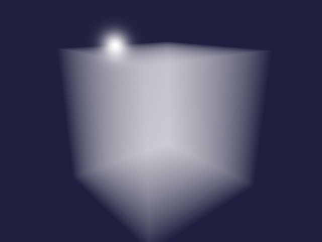
Rendering of 3D noise
This method converts a floating point array to a buffer and initialises a 3D texture with it. It is also necessary to set the texture parameters for interpolation and wrapping.
(defn float-array->texture3d
  [data size]
  (let [buffer  (make-float-buffer data)
        texture (GL11/glGenTextures)]
    (GL11/glBindTexture GL12/GL_TEXTURE_3D texture)
    (GL12/glTexImage3D GL12/GL_TEXTURE_3D 0 GL30/GL_R32F size size size 0
                       GL11/GL_RED GL11/GL_FLOAT buffer)
    (GL11/glTexParameteri GL12/GL_TEXTURE_3D GL11/GL_TEXTURE_MIN_FILTER GL11/GL_LINEAR)
    (GL11/glTexParameteri GL12/GL_TEXTURE_3D GL11/GL_TEXTURE_MAG_FILTER GL11/GL_LINEAR)
    (GL11/glTexParameteri GL12/GL_TEXTURE_3D GL11/GL_TEXTURE_WRAP_S GL11/GL_REPEAT)
    (GL11/glTexParameteri GL12/GL_TEXTURE_3D GL11/GL_TEXTURE_WRAP_T GL11/GL_REPEAT)
    (GL11/glTexParameteri GL12/GL_TEXTURE_3D GL12/GL_TEXTURE_WRAP_R GL11/GL_REPEAT)
    texture))
Here a mixture of 3D Perlin and Worley noise is created.
(def noise3d (dfn/- (dfn/* 0.3 (perlin-noise (make-noise-params 32 4 3)))
                    (dfn/* 0.7 (worley-noise (make-noise-params 32 4 3)))))
The noise is normalised to be between 0 and 1.
(def noise-3d-norm (dfn/* (/ 1.0 (- (dfn/reduce-max noise3d) (dfn/reduce-min noise3d)))
                          (dfn/- noise3d (dfn/reduce-min noise3d))))
Then the noise data is converted to a 3D texture.
(def noise-texture (float-array->texture3d (dtype/->float-array noise-3d-norm) 32))Instead of a constant density fog, we can use the noise as a density function.
(def noise-shader
"#version 130
uniform sampler3D noise3d;
float noise(vec3 idx)
{
  return texture(noise3d, idx).r;
}")
We also set the uniform sampler to texture slot 0 and bind the noise texture to that slot.
(defn setup-noise-uniforms
  [program width height]
  (setup-fog-uniforms program width height)
  (GL20/glUniform1i (GL20/glGetUniformLocation program "noise3d") 0)
  (GL13/glActiveTexture GL13/GL_TEXTURE0)
  (GL11/glBindTexture GL12/GL_TEXTURE_3D noise-texture))
Similar to the fog example above, we define a method to render the noise.
(defn render-noise
  [width height & cloud-shaders]
  (let [fragment-sources (concat cloud-shaders [ray-box fragment-cloud])
        program          (make-program-with-shaders [vertex-passthrough] fragment-sources)
        vao              (setup-quad-vao)]
    (try
      (setup-point-attribute program)
      (render-array width height
                    (setup-noise-uniforms program width height)
                    (GL11/glDrawElements GL11/GL_QUADS 4 GL11/GL_UNSIGNED_INT 0))
      (finally
        (teardown-vao vao)
        (GL20/glDeleteProgram program)))))
Now we can render the mixture of 3D Perlin and Worley noise using a step size of 0.01.
(rgba-array->bufimg
  (render-noise 640 480
                constant-scatter no-shadow (cloud-transfer "noise" 0.01) noise-shader)
  640 480)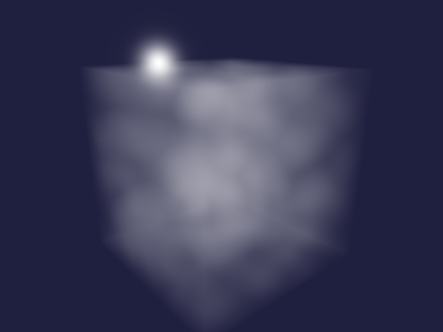
Remap and clamp 3D noise
We define a method to map a range of input values to a range of output values and clamp the result.
(def remap-clamp
"#version 130
float remap_clamp(float value, float low1, float high1, float low2, float high2)
{
  float t = (value - low1) / (high1 - low1);
  return clamp(low2 + t * (high2 - low2), low2, high2);
}")
A probing shader is used to test the remap_clamp function.
(def remap-probe
  (template/fn [value low1 high1 low2 high2]
"#version 130
out vec4 fragColor;
float remap_clamp(float value, float low1, float high1, float low2, float high2);
void main()
{
  fragColor = vec4(remap_clamp(<%= value %>,
                               <%= low1 %>, <%= high1 %>,
                               <%= low2 %>, <%= high2 %>));
}"))
remap_clamp is tested using a parametrized tests.
(tabular "Remap and clamp input parameter values"
       (fact (first (render-pixel
                      [vertex-passthrough]
                      [remap-clamp (remap-probe ?value ?low1 ?high1 ?low2 ?high2)]))
             => ?expected)
       ?value ?low1 ?high1 ?low2 ?high2 ?expected
       0      0     1      0     1      0.0
       1      0     1      0     1      1.0
       0      0     1      2     3      2.0
       1      0     1      2     3      3.0
       2      2     3      0     1      0.0
       3      2     3      0     1      1.0
       1      0     2      0     4      2.0
       0      1     2      1     2      1.0
3 1 2 1 2 2.0)trueWe use the remap-noise method to map the 3D noise to the output range. The base noise function and the remapping parameters are template parameters.
(def remap-noise
  (template/fn [base low1 high1 high2]
"#version 130
float <%= base %>(vec3 idx);
float remap_clamp(float value, float low1, float high1, float low2, float high2);
float remap_noise(vec3 idx)
{
  return remap_clamp(<%= base %>(idx), <%= low1 %>, <%= high1 %>, 0.0, <%= high2 %>);
}"))
We are going to use the following value as the upper value of the cloud density.
(def cloud-strength 6.5)Now we can render the remapped noise values.
(rgba-array->bufimg
  (render-noise 640 480
                constant-scatter no-shadow (cloud-transfer "remap_noise" 0.01)
                remap-clamp (remap-noise "noise" 0.45 0.9 cloud-strength) noise-shader)
  640 480)
Octaves of 3D noise
Earlier we defined a function for creating octaves of 3D noise. Here we create octaves of noise before remapping and clamping the values.
(rgba-array->bufimg
  (render-noise 640 480 constant-scatter no-shadow (cloud-transfer "remap_noise" 0.01)
                remap-clamp (remap-noise "octaves" 0.45 0.9 cloud-strength)
                (noise-octaves (octaves 4 0.5)) noise-shader)
  640 480)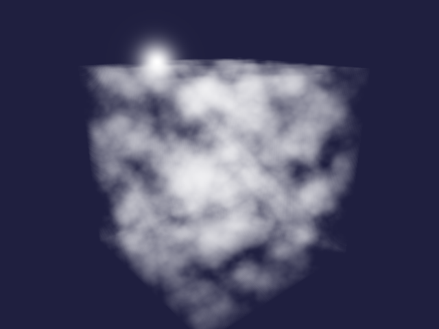
Mie scattering
In-scattering of light towards the observer depends of the angle between light source and viewing direction. Here we are going to use the phase function by Cornette and Shanks which depends on the asymmetry g and mu = cos(theta).
(def mie-scatter
  (template/fn [g]
"#version 450 core
#define M_PI 3.1415926535897932384626433832795
#define ANISOTROPIC 0.25
#define G <%= g %>
uniform vec3 light;
float mie(float mu)
{
  return 3 * (1 - G * G) * (1 + mu * mu) /
    (8 * M_PI * (2 + G * G) * pow(1 + G * G - 2 * G * mu, 1.5));
}
float in_scatter(vec3 point, vec3 direction)
{
  return mix(1.0, mie(dot(light, direction)), ANISOTROPIC);
}"))
We define a probing shader.
(def mie-probe
  (template/fn [mu]
"#version 450 core
out vec4 fragColor;
float mie(float mu);
void main()
{
  float result = mie(<%= mu %>);
  fragColor = vec4(result, 0, 0, 1);
}"))
The shader is tested using a few values.
(tabular "Shader function for scattering phase function"
         (fact (first (render-pixel [vertex-passthrough]
                                    [(mie-scatter ?g) (mie-probe ?mu)]))
               => (roughly ?result 1e-6))
         ?g  ?mu ?result
         0   0   (/ 3 (* 16 PI))
         0   1   (/ 6 (* 16 PI))
         0  -1   (/ 6 (* 16 PI))
         0.5 0   (/ (* 3 0.75) (* 8 PI 2.25 (pow 1.25 1.5)))
0.5 1 (/ (* 6 0.75) (* 8 PI 2.25 (pow 0.25 1.5))))trueWe can define a function to compute a particular value of the scattering phase function using the GPU.
(defn scatter-amount [theta]
  (first (render-pixel [vertex-passthrough] [(mie-scatter 0.76) (mie-probe (cos theta))])))
We can use this function to plot Mie scattering for different angles.
(let [scatter
      (tc/dataset {:x (map (fn [theta]
                               (* (cos (to-radians theta))
                                  (scatter-amount (to-radians theta))))
                           (range 361))
                   :y (map (fn [theta]
                               (* (sin (to-radians theta))
                                  (scatter-amount (to-radians theta))))
                           (range 361)) })]
  (-> scatter
      (plotly/base {:=title "Mie scattering" :=mode "lines"})
      (plotly/layer-point {:=x :x :=y :y})
      plotly/plot
      (assoc-in [:layout :yaxis :scaleanchor] "x")))
We replace the in_scatter placeholder from earlier with the Mie scattering and now the clouds look a bit more realistic.
(rgba-array->bufimg
  (render-noise 640 480 (mie-scatter 0.76) no-shadow (cloud-transfer "remap_noise" 0.01)
                remap-clamp (remap-noise "octaves" 0.45 0.9 cloud-strength)
                (noise-octaves (octaves 4 0.5)) noise-shader)
  640 480)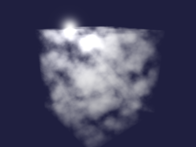
Self-shading of clouds
Finally we can implement the shadow function by also sampling towards the light source to compute the shading value at each point. Testing the function requires extending the render-pixel function to accept a function for setting the light uniform. We leave this as an exercise for the interested reader 😉.
(def shadow
  (template/fn [noise step]
"#version 130
#define STEP <%= step %>
uniform vec3 light;
float <%= noise %>(vec3 idx);
vec2 ray_box(vec3 box_min, vec3 box_max, vec3 origin, vec3 direction);
float shadow(vec3 point)
{
  vec2 interval = ray_box(vec3(-0.5, -0.5, -0.5), vec3(0.5, 0.5, 0.5), point, light);
  float result = 1.0;
  for (float t = interval.x + 0.5 * STEP; t < interval.y; t += STEP) {
    float density = <%= noise %>(point + t * light);
    float transmittance = exp(-density * STEP);
    result *= transmittance;
  };
  return result;
}"))
The final result is starting to look realistic.
(rgba-array->bufimg
  (render-noise 640 480
                (mie-scatter 0.76) (shadow "remap_noise" 0.05)
                (cloud-transfer "remap_noise" 0.01) remap-clamp
                (remap-noise "octaves" 0.45 0.9 cloud-strength)
                (noise-octaves (octaves 4 0.5)) noise-shader)
  640 480)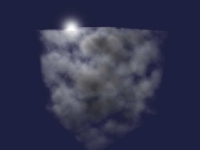
Tidy up
Finally we free the texture, destroy the window, and terminate GLFW.
(GL11/glBindTexture GL12/GL_TEXTURE_3D 0)nil(GL11/glDeleteTextures noise-texture)nil(GLFW/glfwDestroyWindow window)nil(GLFW/glfwTerminate)nilFurther topics
I hope you enjoyed this little tour of volumetric clouds. Here are some references to get from a cloud prototype to more realistic clouds.
- Vertical density profile
- Powder function
- Curl noise
- Precomputed atmospheric scattering
- Deep opacity maps
source: src/volumetric_clouds/main.clj